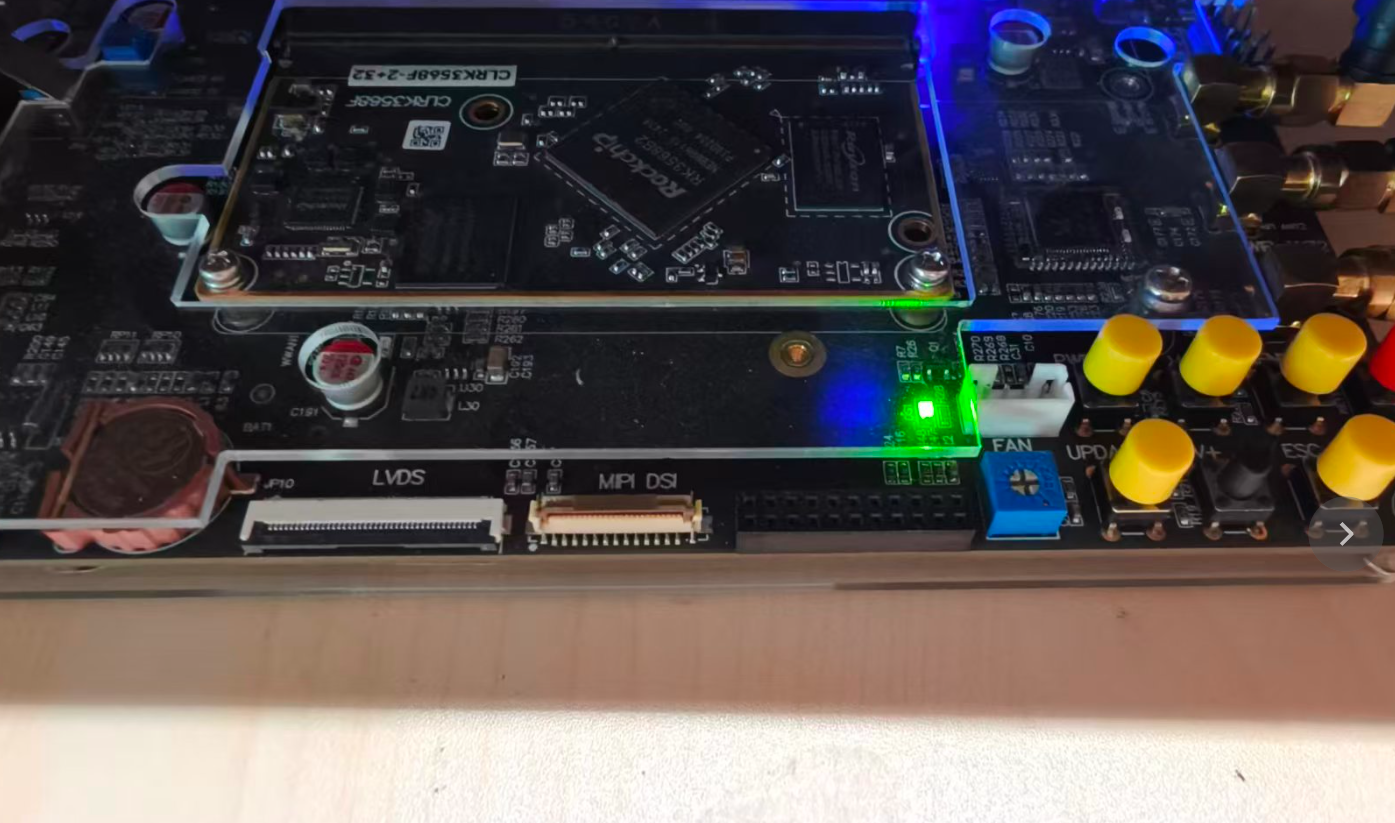
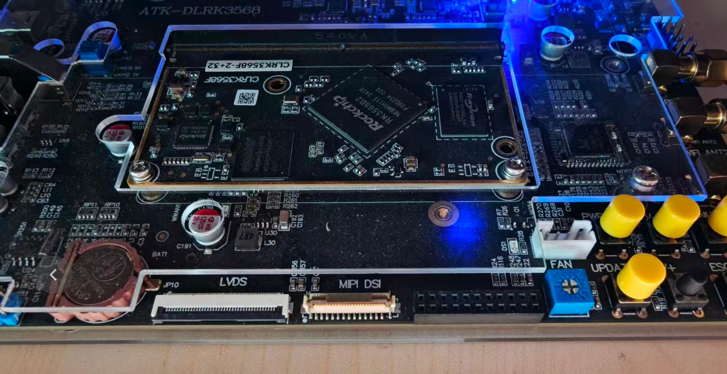
一、确认 LED 在开发板上的引脚位置
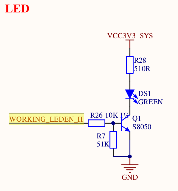
在控制外设之前,首先需要确认该外设连接到芯片的哪个引脚。以板载 LED 为例,在原理图中搜索 LED,可以找到与 WORKING_LEDEN_H 相连的 LED。结合原理图可知:WORKING_LEDEN_H 为高电平时 LED 点亮,为低电平时 LED 熄灭。
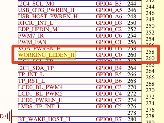
由下图可知,该 LED 连接在 RK3568 的 GPIO0_C0 上。
二、配置 RK3568 的 GPIO 寄存器
无论是 RK3568 还是 STM32,对外设的控制本质上都是对寄存器的读写。需要注意的是,STM32 通常直接操作外设的物理地址;而在 Linux 平台中,内核更多是通过与物理地址对应的虚拟地址来访问寄存器。
物理地址与虚拟地址之间的映射由 MMU(Memory Management Unit)完成。Linux 内核启动时会初始化 MMU 并建立内存映射,随后 CPU 访问的都是虚拟地址。因此,在驱动程序中配置寄存器时,我们不需要关心映射后的虚拟地址具体是多少,只需要使用 ioremap 将寄存器的物理地址映射为可访问的内核虚拟地址,再通过该指针进行读写即可。
在配置 GPIO 之前,需要先明确控制 RK3568 上这颗 LED 涉及哪些寄存器。查阅芯片手册后可知,主要需要配置 PMU_GRF_GPIO0C_IOMUX_L、PMU_GRF_GPIO0C_DS_0 和 GPIO0_SWPORT_DDR_H 这三个寄存器;而 GPIO0_SWPORT_DR_H 则用于设置具体输出的数据。下面逐一说明。
1. 引脚复用设置
RK3568 的一个引脚通常支持多个功能,可以通过 PMU_GRF_GPIO0C_IOMUX_L 寄存器选择当前功能。查阅《Rockchip RK3568 TRM Part1 V1.1-20210301》可知,GPIO0_C0 支持 GPIO、PWM1_M0、GPU_AVS 和 UART0_RX 四种功能。
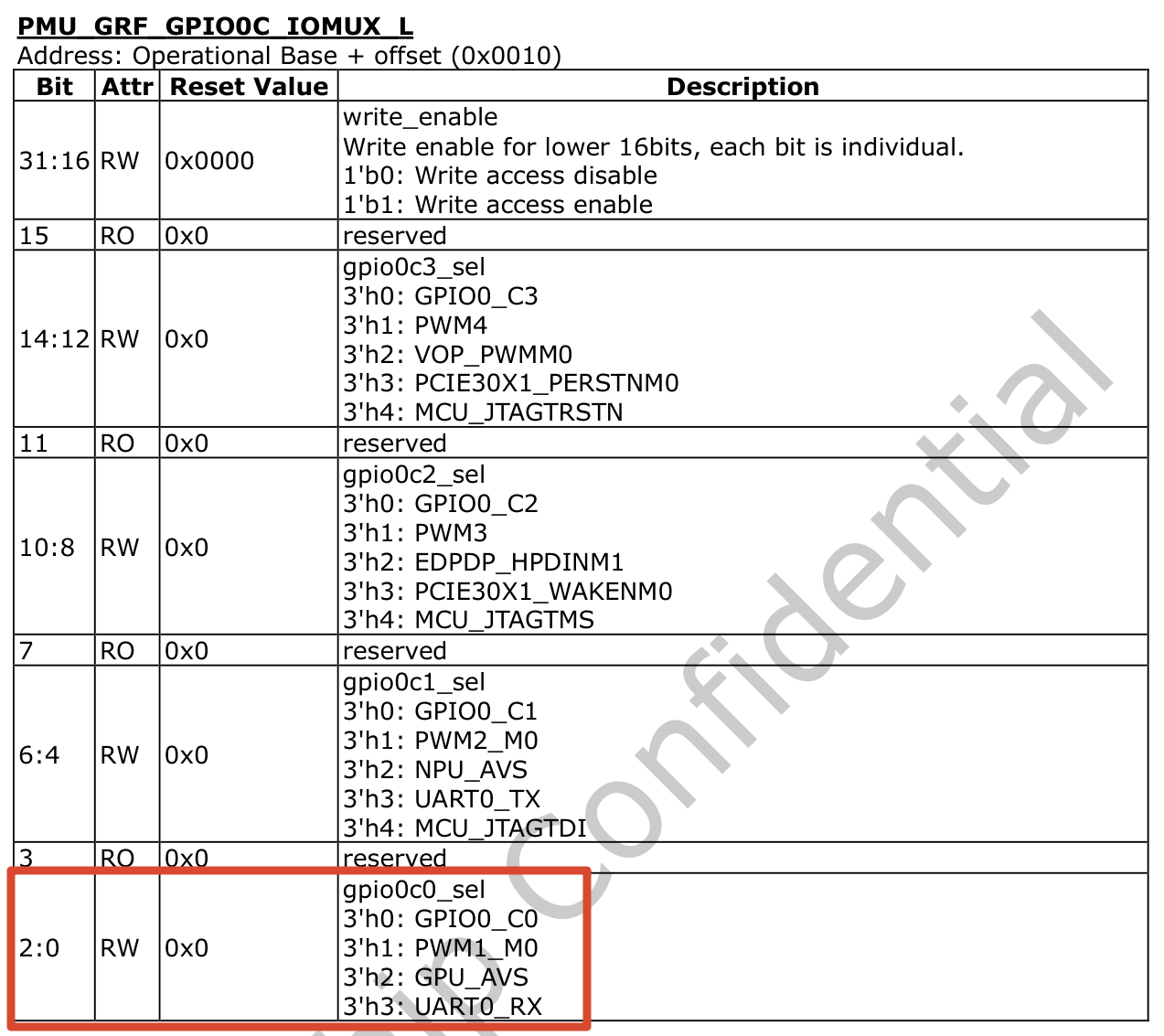
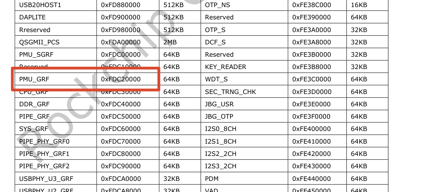
继续查阅手册中 Chapter 1 System Overview 的 address mapping,可以得到 PMU_GRF 的基地址为 0xFDC20000。因此,PMU_GRF_GPIO0C_IOMUX_L 的寄存器地址为 0xFDC20000 + 0x0010,也就是 0xFDC20010。
由于本文需要通过该引脚控制 LED 的亮灭,所以这里要将引脚复用功能设置为普通 GPIO。
2. 引脚驱动能力设置
RK3568 的 IO 引脚支持多级驱动能力配置。驱动能力越高,通常意味着输出等效电阻越小、电平翻转速度越快,也更适合驱动较长的 PCB 走线、更大的输入电容或更高速的信号。
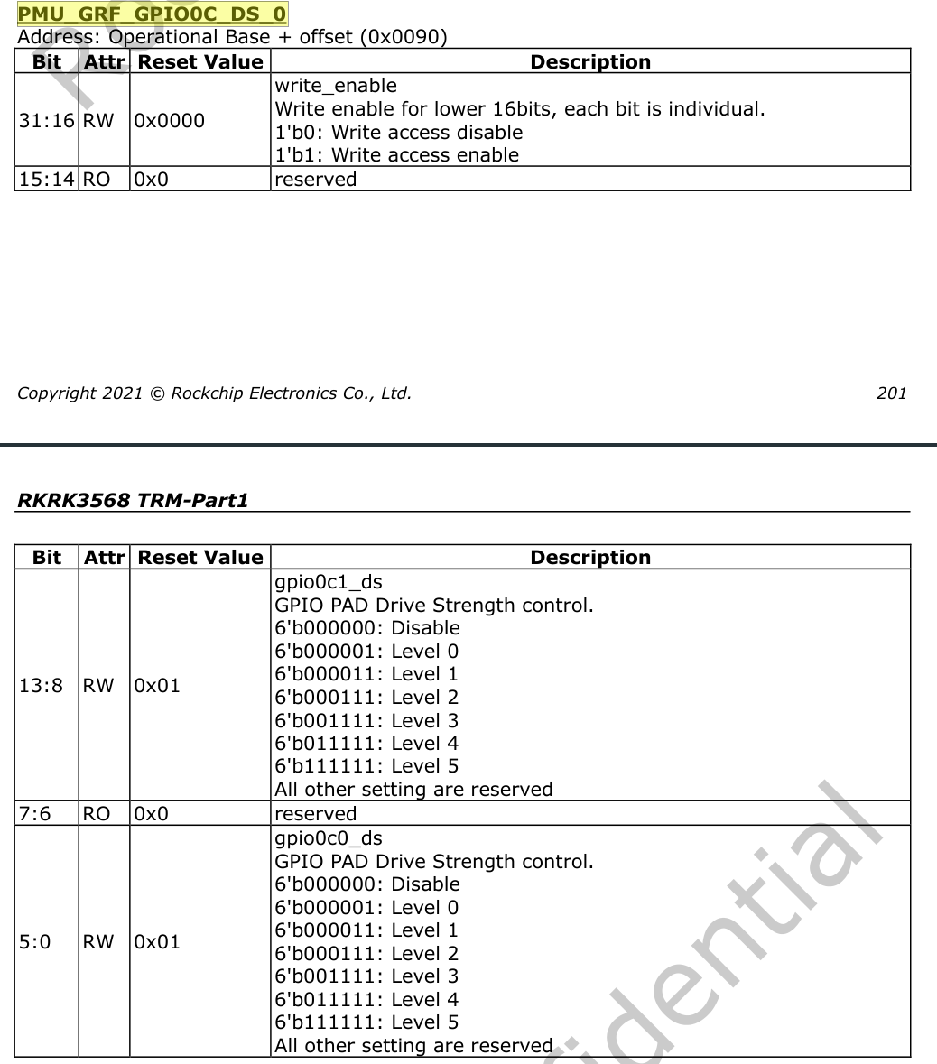
GPIO0_C0 的驱动能力可以通过 PMU_GRF_GPIO0C_DS_0 寄存器进行配置,该寄存器支持 5 个 level。
3. 输入输出设置
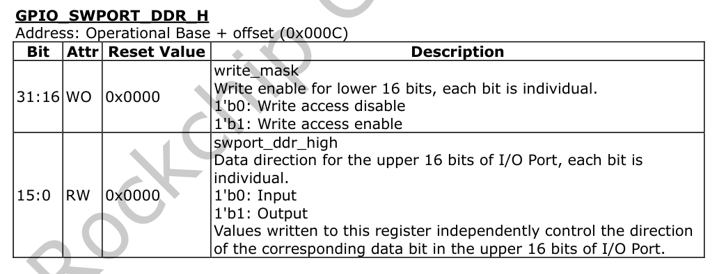
GPIO 是双向引脚,既可以配置为输入,也可以配置为输出。本文用于控制 LED 亮灭,因此需要将 GPIO0_C0 设置为输出模式。对应的方向寄存器是 GPIO_SWPORT_DDR_H,其配置方式与前面的寄存器类似:高 16 位为写使能位,低 16 位为数据位。
| GPIO 组 | GPIOX_A0-A7 | GPIOX_B0-B7 | GPIOX_C0-C7 | GPIOX_D0-D7 |
|---|---|---|---|---|
| 对应的 bit 位 | bit0-bit7 | bit8-bit15 | bit16-bit23 | bit24-bit31 |
| 对应的 DDR 寄存器 | GPIO_SWPORT_DDR_L | GPIO_SWPORT_DDR_L | GPIO_SWPORT_DDR_H | GPIO_SWPORT_DDR_H |
RK3568 一共有 GPIO0 到 GPIO4 共五组 GPIO。其中 GPIO0 到 GPIO3 均包含 A0-A7、B0-B7、C0-C7 和 D0-D7 这 32 个 GPIO,每个 GPIO 需要 1 个 bit 来设置输入或输出方向,因此一组 GPIO 需要 32 bit。GPIO_SWPORT_DDR_L 和 GPIO_SWPORT_DDR_H 就是用来配置这一组 GPIO 输入输出方向的寄存器。
由上表可知,GPIO0_C0 需要使用 GPIO_SWPORT_DDR_H。在该寄存器中,需要将 bit16 置 1 以使能对 bit0 的写操作;同时将 bit0 置 1,将 GPIO0_C0 配置为 output。
4. 引脚电平寄存器设置
本节使用的寄存器与前面略有不同。按我的理解,前面几个更偏向“配置型”寄存器,而这里的 GPIO0_SWPORT_DR_H 更偏向“控制型”寄存器,用于直接控制 GPIO 的输出数据。
操作 GPIO0_C0 时需要用到 GPIO0_SWPORT_DR_H 寄存器,其描述如下:
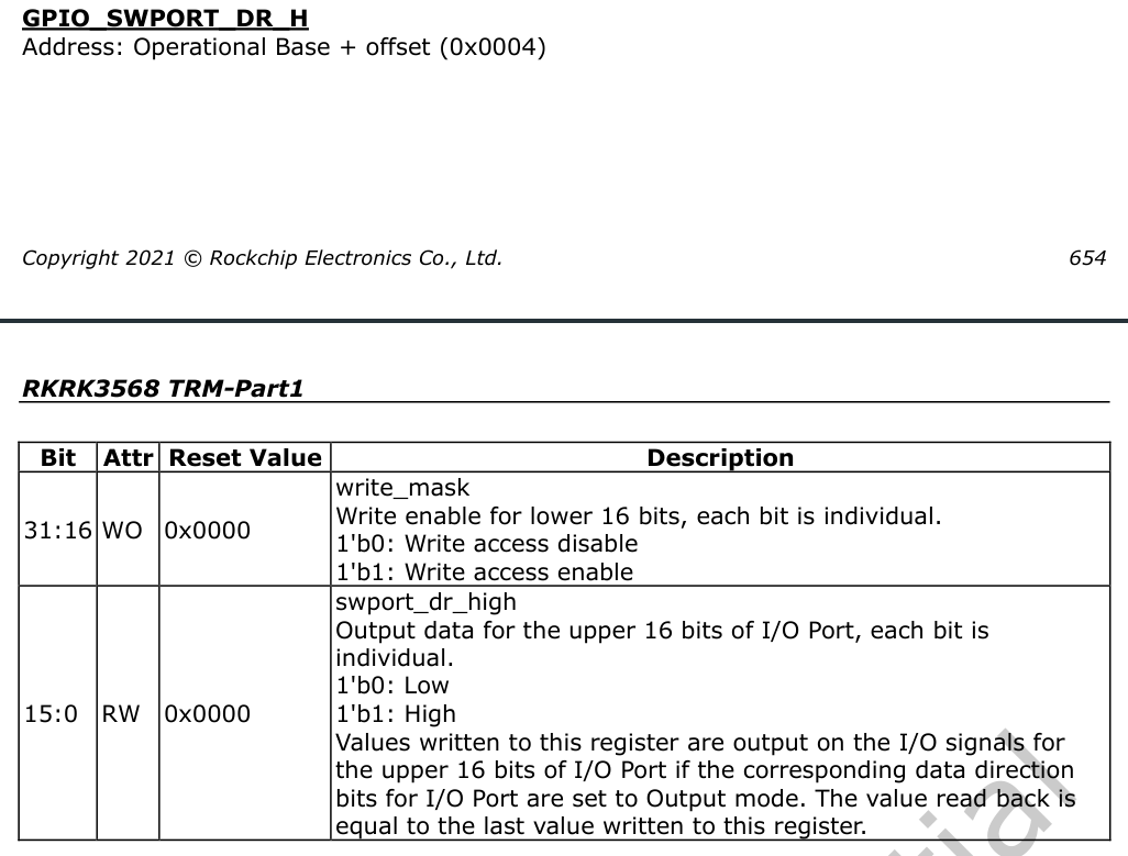
可以看到,它的操作逻辑与上一节的方向寄存器类似。在写使能位有效的情况下,只需要修改对应的数据位,就可以控制该 GPIO 输出高电平或低电平。
三、面向对象、分层与分离的驱动设计思想
在驱动开发中,良好的架构设计不仅影响代码的可读性和可维护性,也会直接影响驱动的扩展性、复用性和稳定性。面向对象、分层设计和分离思想,是驱动开发中非常常见的三种设计方法。
1. 面向对象的驱动设计思想
面向对象思想强调将驱动中的设备、资源和操作抽象成对象。每个对象拥有自己的属性和行为,从而降低模块之间的耦合度。
例如,可以将字符设备抽象为 file_operations 结构体;针对具体硬件,也可以进一步抽象出 led_operations 结构体,用来描述 LED 设备支持的操作。
struct led_operations{
    int num;
    int (*init)(int io);
    int (*write)(int io, int status);
    int (*read)(int io);
};其中,num 表示 LED 的数量,init 表示初始化函数,write 和 read 分别表示写操作和读操作函数。
2. 分层的驱动设计思想
分层设计是将驱动程序按照功能划分为不同层次,每一层只关注自己的职责。
- 上层实现与硬件无关的通用操作,例如在
leddrv.c中注册字符设备驱动。 - 下层实现与硬件相关的具体操作,例如在
board_A.c中实现单板 A 的 LED 控制,并构造对应的led_operations结构体。
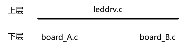
分层设计的核心目标,是让每一层职责单一。上层不直接依赖底层硬件细节,底层也不关心上层业务逻辑。
3. 分离的驱动设计思想
在分层设计的基础上,还可以进一步将“资源”和“操作”分离。
例如,在 board_A.c 中实现一个 led_operations,为 LED 引脚提供初始化函数和读写函数:
static struct led_operations board_demo_led_opr = {
    .num = 1,
    .init = board_demo_led_init,
    .write = board_demo_led_write,
    .read = board_demo_led_read,
};
如果硬件上改用另一个引脚来控制 LED,直接修改这些函数当然可以实现,但维护成本会比较高。实际上,同一款芯片的 GPIO 操作方式通常是类似的,并且这部分逻辑与主控芯片关系更大。基于这个特点,可以为芯片编写更通用的 GPIO 操作代码。
例如,board_A.c 使用的是 chipY,就可以编写 chipY_gpio.c 来封装芯片 Y 的 GPIO 操作,使其适用于芯片 Y 的所有 GPIO 引脚。具体到某块板子时,只需要在 board_A_led.c 中指定使用哪一个引脚即可。
其程序结构如下:
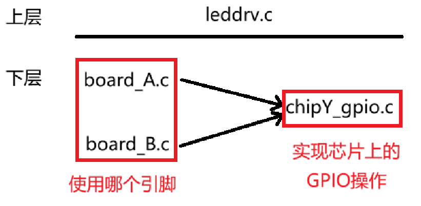
按照这种思路,可以在 board_A_led.c 中实现 led_resource 结构体,用它描述“资源”,也就是具体使用哪一个引脚;而在 chipY_gpio.c 中继续实现 led_operations 结构体,用它封装更通用的 GPIO 初始化、读写和控制能力。
四、编写驱动程序
1. 定义 led_opr.h
// led_opr.h
#ifndef _LED_OPR_H
#define _LED_OPR_H

struct led_operations{
    int num;
    int (*init)(int io);
    int (*write)(int io, int status);
    int (*read)(int io);
};

struct led_operations* get_board_led_opr(void);

#endif
2. 编写板级支持层
// board_rk3568.c
#include <linux/module.h>

#include <linux/fs.h>
#include <linux/errno.h>
#include <linux/miscdevice.h>
#include <linux/kernel.h>
#include <linux/major.h>
#include <linux/mutex.h>
#include <linux/proc_fs.h>
#include <linux/seq_file.h>
#include <linux/stat.h>
#include <linux/init.h>
#include <linux/device.h>
#include <linux/tty.h>
#include <linux/kmod.h>
#include <linux/gfp.h>
#include <asm/io.h>
#include "led_opr.h"

#define PMU_GRF_BASE             0xFDC20000
// #define PMU_GRF_GPIO0C_IOMUX_L   (PMU_GRF_BASE+0x10)
// #define PMU_GRF_GPIO0C_DS_0      (PMU_GRF_BASE+0x90)

#define GPIO0_BASE               0xFDD60000
// #define GPIO0_SWPORT_DR_H        (GPIO0_BASE+0x04)
// #define GPIO0_SWPORT_DDR_H       (GPIO0_BASE+0x0C)


static volatile unsigned int* PMU_GRF_GPIO0C_IOMUX_L; // 处理 GPIO 复用
static volatile unsigned int* PMU_GRF_GPIO0C_DS_0;    // 引脚驱动能力设置
static volatile unsigned int* GPIO0_SWPORT_DR_H;      // 输入输出数据寄存器
static volatile unsigned int* GPIO0_SWPORT_DDR_H;     // 输入输出方向设置

static int board_rk3568_led_init(int io){
    uint32_t val;

    // 寄存器地址映射
    PMU_GRF_GPIO0C_IOMUX_L = ioremap(PMU_GRF_BASE+0x0010, 4);
    PMU_GRF_GPIO0C_DS_0 = ioremap(PMU_GRF_BASE+0x0090, 4);
    GPIO0_SWPORT_DR_H = ioremap(GPIO0_BASE+0x0004, 4);
    GPIO0_SWPORT_DDR_H = ioremap(GPIO0_BASE+0x000c, 4);

    // 引脚复用设置为普通 GPIO 口
    val = readl(PMU_GRF_GPIO0C_IOMUX_L);
    val &= ~(0x07 << 0);
    val |= ((0x07 << 16) | (0x00 << 0));
    writel(val, PMU_GRF_GPIO0C_IOMUX_L);

    // 将 GPIO0_C0 的引脚驱动能力设置为 5 级
    val = readl(PMU_GRF_GPIO0C_DS_0);
    val &= ~(0x3f << 0);
    val |= ((0x3f << 16) | (0x3f << 0));
    writel(val, PMU_GRF_GPIO0C_DS_0);

    // 设置 GPIO0_C0 为输出模式
    val = readl(GPIO0_SWPORT_DDR_H);
    val &= ~(0x01 << 0);
    val |= ((0x01 << 16) | (0x01 << 0));
    writel(val, GPIO0_SWPORT_DDR_H);

    return 0;
}

static int board_rk3568_led_write(int io, int status){
    uint32_t val;
    if(status == 1){
        val = readl(GPIO0_SWPORT_DR_H);
        val &= ~(0x01 << 0);
        val |= ((0x01 << 16) | (0x01 << 0));
        writel(val, GPIO0_SWPORT_DR_H);
        printk("led置1\n");
    }
    else if(status == 0){
        val = readl(GPIO0_SWPORT_DR_H);
        val &= ~(0x01 << 0);
        val |= ((0x01 << 16) | (0x00 << 0));
        writel(val, GPIO0_SWPORT_DR_H);
        printk("led置0\n");
    }
    else{
        // 输入的 status 非法
        return -1;
    }

    return 0;
}

static int board_rk3568_led_read(int io){
    int status = 0;

    *GPIO0_SWPORT_DR_H &= ~(0x00010001);
    *GPIO0_SWPORT_DR_H |= 0x00010000;

    if((*GPIO0_SWPORT_DR_H&0x00000001) == 0x00000001){
        status = 1;
    }
    else if((*GPIO0_SWPORT_DR_H&0x00000001) == 0x00000000){
        status = 0;
    }

    return status;
}

// 注册板级 LED 操作
static struct led_operations board_rk3568_led_opr = {
    .init = board_rk3568_led_init,
    .write = board_rk3568_led_write,
    .read = board_rk3568_led_read
};

struct led_operations* get_board_led_opr(void){
    return &board_rk3568_led_opr;
}
3. 编写设备驱动层
// led_dev.c
#include <linux/module.h>

#include <linux/fs.h>
#include <linux/errno.h>
#include <linux/miscdevice.h>
#include <linux/kernel.h>
#include <linux/major.h>
#include <linux/mutex.h>
#include <linux/proc_fs.h>
#include <linux/seq_file.h>
#include <linux/stat.h>
#include <linux/init.h>
#include <linux/device.h>
#include <linux/tty.h>
#include <linux/kmod.h>
#include <linux/gfp.h>
#include "led_opr.h"


// 确定设备号
static int major;
static struct class* led_class;
struct led_operations *p_led_opr;

// 打开设备
static int led_open(struct inode *inode, struct file *filp){
    p_led_opr->init(0);
    printk("led initial success!\n");
    return 0;
}

// 关闭设备
static int led_release(struct inode *inode, struct file *filp){
    printk("led close success!\n");
    return 0;
}

// 从内核设备读取数据
static ssize_t led_read(struct file *filp, char __user *buf, size_t len, loff_t *offset){
    int err;
    int status = 0;
    status = p_led_opr->read(0);
    err = copy_to_user(buf, &status, sizeof(status));
    if (err != 0) {
        return -EFAULT;
    }
    return 0;
}

// 向内核设备写入数据
static ssize_t led_write(struct file *filp, const char __user *buf, size_t len, loff_t *offset){
    int err;
    int status = 0;
    err = copy_from_user(&status, buf, sizeof(status));
    if (err != 0) {
        return -EFAULT;
    }
    p_led_opr->write(0, status);
    printk("内核收到的status = %d\n", status);
    return 0;
}

static struct file_operations led_fops = {
    .owner = THIS_MODULE,
    .open = led_open,
    .read = led_read,
    .write = led_write,
    .release = led_release
};

// 注册驱动程序,安装驱动时调用该函数
static int __init led_init(void){
    int err;

    // 注册主设备号
    major = register_chrdev(0, "led", &led_fops); // /dev/led

    led_class = class_create(THIS_MODULE, "led_class");
    err = PTR_ERR(led_class);
    if(IS_ERR(led_class)){
        printk("%s %s line %d\n", __FILE__, __FUNCTION__, __LINE__);
        unregister_chrdev(major, "led");
        return -1;
    }

    // 初始化 GPIO 操作
    p_led_opr = get_board_led_opr();

    // 创建设备
    device_create(led_class, NULL, MKDEV(major, 0), NULL, "led");

    return 0;
}

// 卸载模块
static void __exit led_exit(void){
    // 卸载设备
    device_destroy(led_class, MKDEV(major, 0));
    class_destroy(led_class);
    unregister_chrdev(major, "led");
}

module_init(led_init);
module_exit(led_exit);

MODULE_LICENSE("GPL");
4. 修改 Makefile 文件
# Makefile
KERNELDIR := /root/rk3568/rk3568_linux_sdk/kernel
PWD := $(shell pwd)

ARCH ?= arm64
CROSS_COMPILE ?= aarch64-buildroot-linux-gnu-
TOOLCHAIN_DIR ?= /opt/atk-dlrk3568-5_10_sdk-toolchain/bin

obj-m := led_drv.o

led_drv-objs := led_dev.o board_rk3568.o

all:
	PATH=$(TOOLCHAIN_DIR):$$PATH $(MAKE) -C $(KERNELDIR) \
		ARCH=$(ARCH) CROSS_COMPILE=$(CROSS_COMPILE) \
		M=$(PWD) modules

clean:
	PATH=$(TOOLCHAIN_DIR):$$PATH $(MAKE) -C $(KERNELDIR) \
		ARCH=$(ARCH) CROSS_COMPILE=$(CROSS_COMPILE) \
		M=$(PWD) clean
五、编写测试程序并完成上板测试
1. 编写测试程序
测试程序主要完成两件事:控制 LED 亮灭,以及读取当前 LED 状态。示例代码如下:
#include <stdio.h>
#include <fcntl.h>
#include <stdlib.h>
#include <unistd.h>
#include <string.h>

int main(int argc, char *argv[])
{
    int status = 0;
    char *fileName = argv[1];
    int fd;
    fd = open(fileName, O_RDWR);
    if (fd < 0) {
        printf("Cannot open file %s\n", fileName);
        return -1;
    }

    // 读取当前 LED 状态
    if(atoi(argv[2])==1){
        int readLen = read(fd, &status, sizeof(status));
        if(readLen < 0){
            printf("读取LED状态失败\n");
            return -1;
        }
        else{
            if(status==0){
                printf("%s :当前LED已经熄灭\n", fileName);
            }
            else{
                printf("%s :当前LED已经点亮\n", fileName);
            }
        }
    }

    // 设置 LED 状态
    if(atoi(argv[2])==2){
        int writeBit = atoi(argv[3]);
        int writeLen = write(fd, &writeBit, sizeof(writeBit));
        if(writeLen < 0){
            printf("点亮LED失败\n");
            return -1;
        }
        else{
            printf("控制成功\n");
        }
    }

    if(close(fd) < 0) {
        printf("Cannot close file %s\n", fileName);
        return -1;
    }
    return 0;
}
2. 完成上板测试
终端测试流程如下:
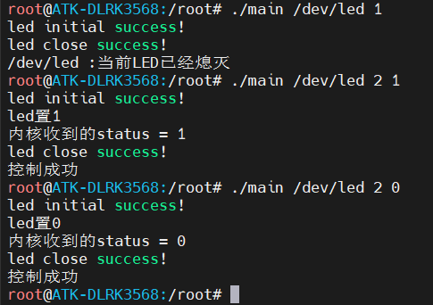
实验现象如下: